NL4FX Wiring: The Pinout and Safe Variants
The questionWhere do these come from?
Wiring a 2 Channel Behringer NX3000 to a Dayton DVC Subwoofer MX15-22
Hi, I have 15" Dayton DVC MX15-22 subwoofer in a ported enclosure I'll be using in a garage (don't care about fan noise). I want to try out this amp but I'm not sure how to wire it correctly, and also what connectors to use.
Wire a standard NL4FX cable pin-for-pin: 1+ to 1+, 1− to 1−, 2+ to 2+, and 2− to 2−; bridge and DVC setups need extra checks.
For a normal speaker cable, wire the Neutrik NL4FX straight through: 1+ to 1+, 1− to 1−, 2+ to 2+, and 2− to 2−. With two-conductor cable, use only 1+ and 1− unless the amplifier or speaker manual explicitly assigns the signal to another pair.
STANDARD NL4FX-TO-NL4FX CABLE

Amplifier end                  Speaker end
    1+  ──────────────────────────  1+
    1−  ──────────────────────────  1−
    2+  ──────────────────────────  2+
    2−  ──────────────────────────  2−

Two-conductor version:
    1+  ──────────────────────────  1+
    1−  ──────────────────────────  1−
    2+  not connected
    2−  not connected
This is a logical diagram, not a drawing of the contact positions. Front and rear views are mirrored, so identify each terminal by the 1+, 1−, 2+, or 2− marking molded beside it, not by its clock position. Neutrik’s assembly sheet shows all four terminal markings on the insert.Neutrik NL4FX assembly instructions
The straight-through cable most systems expect
The NL4FX contains two independent conductor pairs. The usual assignments are:
| NL4FX terminal | Normal assignment | Two-core cable |
|---|---|---|
| 1+ | Speaker circuit A positive | Connect |
| 1− | Speaker circuit A negative | Connect |
| 2+ | Speaker circuit B positive | Leave unused |
| 2− | Speaker circuit B negative | Leave unused |
In an ordinary passive full-range speaker or single-channel subwoofer connection, the amplifier’s positive output goes to 1+ and its negative output goes to 1−. Keep the same assignment at the speaker end.
Four-core cable does not require all four contacts to feed one speaker. It merely makes the second pair available. Neutrik’s own wiring guide shows 1+/1− and 2+/2− carrying separate left/right channels or separate low- and high-frequency amplifier feeds.Neutrik speakON wiring suggestions
Strip and terminate the NL4FX correctly
Disconnect and unplug the amplifier before opening or wiring the connector. Neutrik marks the NL4FX “not for interrupting current,” meaning it should not be used as an on-load switch. It is a loudspeaker connector and must not be repurposed for AC mains or general power-supply wiring.
- Slide the threaded bushing and strain-relief chuck onto the cable before terminating any conductors.
- Remove 25 mm of the outer jacket.
- Strip 12 mm of insulation from each conductor being used.
- Insert each conductor into its labeled terminal. On thick four-core cable, Neutrik recommends fastening the inner 1+ and 2+ contacts before the outer 1− and 2− contacts.
- Tighten the clamp screws with a Pozidriv PZ1 screwdriver, not a Phillips driver. The specified maximum terminal-screw torque is 0.8 N·m.
- Align the chuck’s locating nose with the housing recess, push it into position, and tighten the rear bushing.
The original NL4FX accepts cable with an outside diameter of 7–14.5 mm. Its screw terminals accept conductors up to 4 mm²/12 AWG; Neutrik specifies removing the screws and clamp sheets and soldering when using 6 mm²/10 AWG conductors.Neutrik NL4FX specifications
Do not tin stranded wire before placing it under the screw clamp. The connector includes a pressure plate intended to retain bare stranded conductors. Solder can creep under sustained pressure and allow a previously tight screw termination to loosen.
Bridge-mono wiring starts with the amplifier manual
Do not assume bridge mode uses 1+ and 1−. A common bridge assignment is 1+ for speaker positive and 2+ for speaker negative, with 1− and 2− unused, but that convention is not universal.
For example, Behringer’s EUROPOWER PMP6000/PMP4000/PMP1000 documentation assigns its bridge output across 1+ and 2+ on Output B.Behringer EUROPOWER PMP-series manual Neutrik also illustrates a special bridge cable using 1+/2+, but the power amplifier’s manual—not the connector—remains authoritative.
COMMON BRIDGE-MODE AMPLIFIER END
VERIFY THIS AGAINST THE EXACT AMPLIFIER MANUAL

Amp bridge positive  ───────────────  1+
Amp bridge negative  ───────────────  2+
                                      1− unused
                                      2− unused
The speaker end still has to match the cabinet’s input wiring. If the cabinet accepts its driver on 1+/1−, a purpose-built bridge cable may need:
Amplifier end 1+  ─────────  Speaker end 1+
Amplifier end 2+  ─────────  Speaker end 1−
That cable is deliberately not straight-through and should be labeled at both ends. A normal four-core pin-for-pin cable will work only when the cabinet is also wired to receive the bridged signal across 1+ and 2+.
Never infer bridge wiring from another amplifier in the same rack. An incorrect assignment may produce silence, reverse polarity, connect the wrong channel, or short an amplifier output.
Just want the recommendation?
Skip to the picksA DVC subwoofer changes the load, not the pin names
A dual-voice-coil subwoofer does not automatically require all four NL4FX contacts. When both coils are powered from one amplifier channel, connect the coils in series or parallel inside the cabinet, then present the resulting single load on 1+/1−.
Parallel coils:
NL4FX 1+ ──┬── Coil 1 +
            └── Coil 2 +

NL4FX 1− ──┬── Coil 1 −
            └── Coil 2 −
Series coils:
NL4FX 1+ ─── Coil 1 +
              Coil 1 − ─── Coil 2 +
                           Coil 2 − ─── NL4FX 1−
For equal coils, parallel wiring halves the nominal impedance while series wiring doubles it. Two 4-ohm coils therefore produce a 2-ohm parallel load or an 8-ohm series load; two 2-ohm coils produce 1 ohm in parallel or 4 ohms in series. Kicker’s technical paper documents the same calculations and stresses observing polarity.Kicker series and parallel speaker-wiring guide
Check that final load against the amplifier’s minimum supported impedance, especially in bridge mode. Bridging and paralleling DVC coils simultaneously can produce a load the amplifier cannot safely drive.
The four contacts can instead expose the coils separately:
1+ / 1−  ─── Voice coil 1 + / −
2+ / 2−  ─── Voice coil 2 + / −
Do this only when the subwoofer and amplifier documentation explicitly supports independent coil feeds. Driving the coils from two channels with different signals, gains, limiters, or polarity makes the coils fight each other mechanically. Wiring both coils in series or parallel to one approved amplifier output is the safer default.
Bi-amp and two-channel cables use the second pair
A four-conductor pin-for-pin cable can carry two amplifier circuits through one NL4FX. Common arrangements include channel A on 1+/1− and channel B on 2+/2−, or low frequency on 1+/1− and high frequency on 2+/2−. Some systems reverse the frequency assignment: Behringer’s NX bi-amping example places high frequency on 1+/1− and low frequency on 2+/2−.Behringer NX-series quick-start guide
This is why “2+ is always channel B” is not a safe rule. The connector names four electrical contacts; the connected equipment determines what those contacts carry.
Prove the cable before powering the amplifier
Test a completed cable while it is disconnected at both ends. Fluke’s continuity guidance likewise specifies testing a de-energized, isolated circuit.Fluke continuity-testing guide
- Set a multimeter to continuity or its lowest resistance range.
- Confirm 1+ at one end connects only to the intended terminal at the other end.
- Repeat for 1−, 2+, and 2−.
- Check every unlike pair—such as 1+ to 1− and 1+ to 2+—for an open circuit.
- Flex the cable near both strain reliefs while testing to expose an intermittent conductor.
For a two-core cable, only the intended two end-to-end paths should conduct. For a four-core straight-through cable, there should be four paths and no cross-connections.
No independent laboratory appears to have published a full NL4FX performance evaluation. One documented bench test by audio technician B. Jobst measured approximately 1.5 mΩ directly across a fresh NL4FX mated with an NL4MPR socket. That is a single-sample measurement rather than certification, but it provides a useful check against Neutrik’s stated contact resistance of under 2 mΩ after its lifetime test.Jobst Audio connector-resistance measurements
The NL4FX itself is discontinued. Neutrik names the NL4FXX-W-S for 6–12 mm cable and NL4FXX-W-L for 10–16 mm cable as its direct successors. Existing NL4FX connectors remain wireable using the diagram and assembly values above; for a new build, choose the successor whose strain-relief range actually matches the cable diameter.
The bottom line
Either works — what you already have picks one:
Top pick
It depends
Neutrik NL4FXX-W-S 4 pole speakON cable connector
Neutrik
It suits 6–12 mm cable but cannot properly clamp thicker 12–16 mm touring cable.
Use this current NL4FX successor when the speaker cable’s outside diameter is 6–12 mm. Its drawback is that it cannot properly clamp thicker 12–16 mm touring cable.Available at Amazon(paid link) — opens Amazon in a new tab. Price and availability shown there.The alternative
It depends
Neutrik NL4FXX-W-L 4 pole speakON cable connector
Neutrik
It suits 10–16 mm cable, but its strain relief may not securely grip thin cable.
Choose the large-bushing successor for 10–16 mm cable. It is the wrong version for thin cable because the strain relief may not grip it securely.Available at Amazon(paid link) — opens Amazon in a new tab. Price and availability shown there.
Recommended products
Ordered by how well each one fits the situations above. Each link below is a paid link.

Neutrik NL4FXX-W-S 4 pole speakON cable connector
Neutrik
It depends — It suits 6–12 mm cable but cannot properly clamp thicker 12–16 mm touring cable.
Use this current NL4FX successor when the speaker cable’s outside diameter is 6–12 mm. Its drawback is that it cannot properly clamp thicker 12–16 mm touring cable.Available at Amazon(paid link) — opens Amazon in a new tab. Price and availability shown there.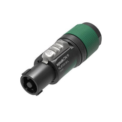
Neutrik NL4FXX-W-L 4 pole speakON cable connector
Neutrik
It depends — It suits 10–16 mm cable, but its strain relief may not securely grip thin cable.
Choose the large-bushing successor for 10–16 mm cable. It is the wrong version for thin cable because the strain relief may not grip it securely.Available at Amazon(paid link) — opens Amazon in a new tab. Price and availability shown there.Wera Kraftform Plus 355 PZ 1 screwdriver
Wera Kraftform
Buy — The NL4FX assembly procedure specifies a Pozidriv PZ1 screwdriver rather than a Phillips driver.
The original NL4FX terminal screws require a PZ1 driver; this avoids damaging them with a Phillips tip. It is not torque-limiting, so it cannot verify Neutrik’s 0.8 N·m maximum.Available at Amazon(paid link) — opens Amazon in a new tab. Price and availability shown there.
Klein Tools MM325 digital multimeter
Klein Tools
Buy — The article recommends multimeter continuity testing to verify the intended conductor paths and detect cross-connections before powering the amplifier.
Continuity mode lets you verify every NL4 path and detect accidental cross-connections before applying amplifier power. It is a manual-ranging meter and is more tool than a single cable build strictly requires.Available at Amazon(paid link) — opens Amazon in a new tab. Price and availability shown there.
Sources
Pages consulted while researching this article. None of these are affiliate links.
- Neutrik NL4FX/NL4FRX Assembly Instructions — neutrik.com
- Neutrik NL4FX Product Specifications — neutrik.com
- Neutrik speakON Wiring Suggestions — neutrik.com
- Behringer EUROPOWER PMP6000/PMP4000/PMP1000 User Manual — mediadl.musictribe.com
- Behringer NX Series Quick Start Guide — mediadl.musictribe.com
- Kicker Series, Parallel, and Series-Parallel Speaker Wiring — kicker.com
- Fluke Guide to Continuity Testing with a Multimeter — fluke.com
- Jobst Audio Connector Contact-Resistance Measurements — lautsprecherforum.eu